Heavy Tonnage Force Measurement (10 MN – 50+ MN)
Moving beyond hydraulic ΔP estimates. Direct-measurement load cell architectures for aerospace and heavy civil infrastructure validation.
The Parametric Design Envelope
At the extremes of heavy-tonnage validation, off-the-shelf catalog sensors introduce unacceptable compromises.
Custom Capabilities:
Capacity Range: 1 MN to 50+ MN (Tension, Compression, or Universal).
Architecture: Precision Column, Heavy Tubular, or Modular Multi-Piece.
Redundancy: Single, Dual, or Triple redundant Wheatstone bridge arrays (350Ω or 1000Ω).
Output Sensitivity: 1.5 mV/V to 2.0 mV/V (Customized to DAQ input limits).
Kinematic Rejection: Native geometric hardware balancing combined with custom linear compensation matrices (e.g., strict Fz isolation with Mx/My rejection).
Seamless Integration: Custom-machined mechanical adapters and interface flanges designed to mate directly with all major large-scale load frame manufacturers or custom compression platens.
Aerospace Grade: The Precision Column Series (SE-HC-A)
Engineered strictly for aerospace fatigue and ultimate load testing. By utilizing a precision-machined central column structure, we intentionally maximize localized strain at the internal gauge sites. This allows us to stack up to three independent Wheatstone bridges on a single column, providing the triple-redundancy required for mission-critical flight hardware validation.
Below is the technical matrix for our standard aerospace column architectures.
| Specification | SE-HC-10A | SE-HC-20A | SE-HC-30A |
|---|---|---|---|
| Load Capacity | 10 MN (2.2M lbf) | 20 MN (4.5M lbf) | 30 MN (6.7M lbf) |
| Calibratable Range (NIST Limit) | 4.448 MN (1M lbf) | 4.448 MN (1M lbf) | 4.448 MN (1M lbf) |
| Accuracy (Under Calibration) | ± 0.1% Full Scale | ± 0.1% Full Scale | ± 0.1% Full Scale |
| Expected Extrapolated Accuracy | ± 0.15% Full Scale | ± 0.15% Full Scale | ± 0.15% Full Scale |
| Redundant Bridges | 1, 2, or 3 | 1, 2, or 3 | 1, 2, or 3 |
| Connector Type | Mil-Spec 6-Pin | Mil-Spec 6-Pin | Mil-Spec 6-Pin |
| TEDS Compatibility | Yes (IEEE 1451.4) | Yes (IEEE 1451.4) | Yes (IEEE 1451.4) |
| Precision Shunt Resistor | Yes (Integrated) | Yes (Integrated) | Yes (Integrated) |
*Note: Bridge count and connector configuration (e.g., PT02E-10-6P per bridge) are customized based on the facility's specific Data Acquisition (DAQ) channels.
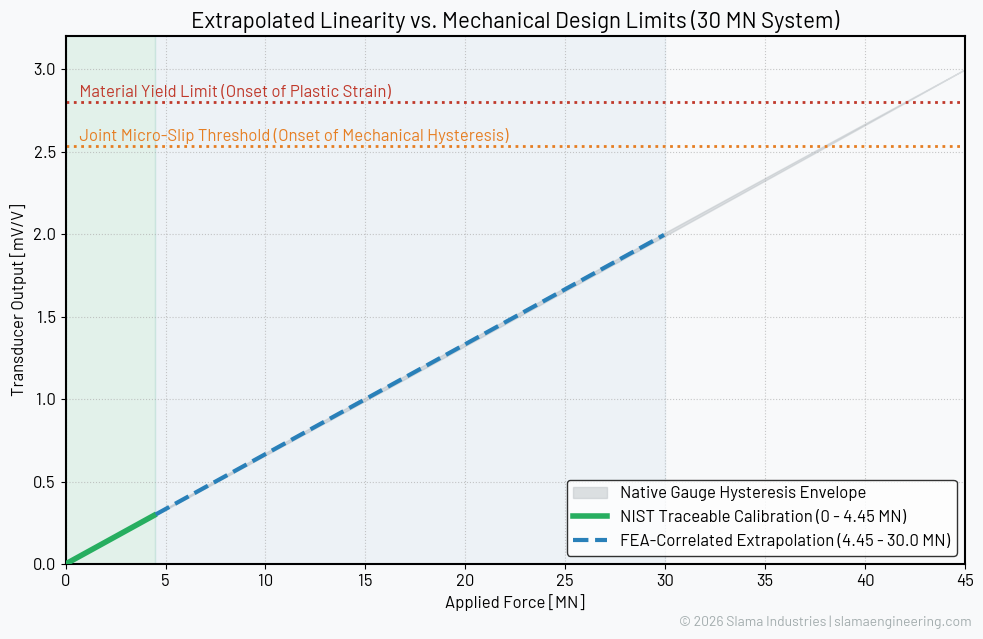
The Hysteresis Scaling Factor
When evaluating extrapolated data, structural engineers often question system hysteresis at massive loads. The graph above illustrates our mechanical safety margins. Because we over-engineer the transducer's clamped joints to prevent micro-slippage entirely, mechanical hysteresis is eliminated. The only remaining hysteresis is the native behavior of the polyimide strain gauge itself. High-performance foil gauges exhibit hysteresis that scales linearly with full-scale output. Because our systems remain strictly within the linear elastic region well past 30 MN, the relative hysteresis percentage validated at 4.45 MN remains identical at full capacity.
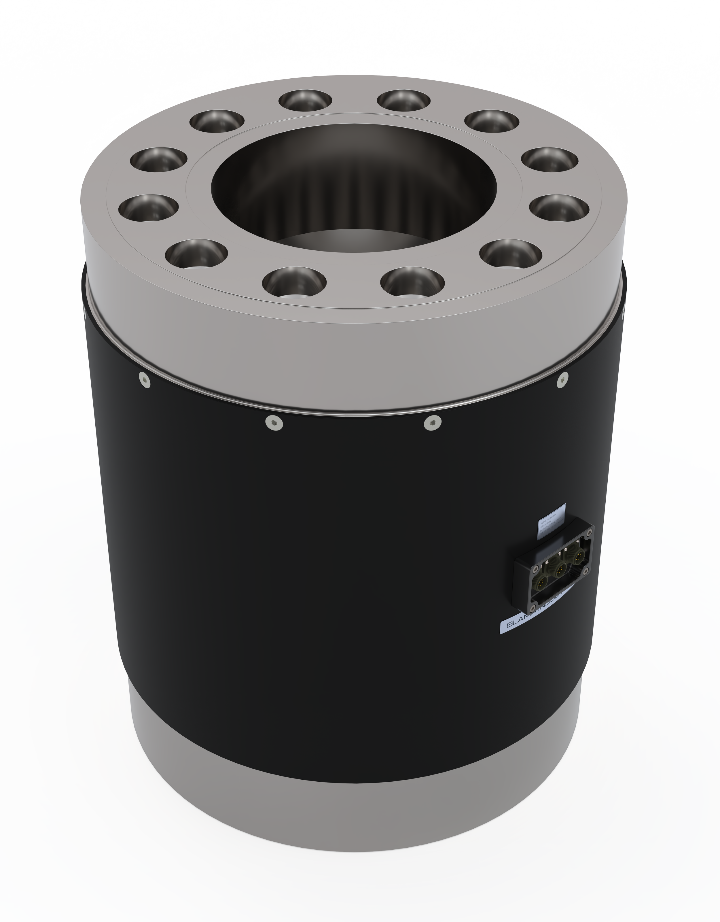
Heavy Civil Grade: The Tubular Structure (30+ MN)
When crushing high-performance concrete or massive bridge piers, vertical packaging space is often limited, and the release of energy during a catastrophic failure is violent. For applications exceeding 30 MN, we deploy a thick-walled tubular architecture. This provides a dramatically lower vertical profile and massive, unyielding structural stiffness to survive explosive test-article failures without sustaining zero-shift damage.
Specialized Infrastructure: The Modular Assembly
Designed specifically for large civil panel crack fatigue tests where massive, off-axis bending moments are applied to the test frame. A monolithic load cell cannot survive these isolated moments at this scale. We architect a multi-piece assembly utilizing a matrix of highly matched, parallel-instrumented load elements. This completely isolates the axial load from the parasitic moments and solves the logistical nightmare of machining and transporting a single 10,000 lb block of steel.
Measurement Certainty: Eliminating the Friction Variable
In heavy infrastructure and large-scale structural testing, force is traditionally derived by measuring the differential pressure ($\Delta P$) across the hydraulic actuator. While Δ is highly effective for general industrial use, it inherently masks the mechanical seal friction and dynamic bind of the hydraulic cylinder.
When safety-critical validation is on the line, estimating friction is no longer acceptable.
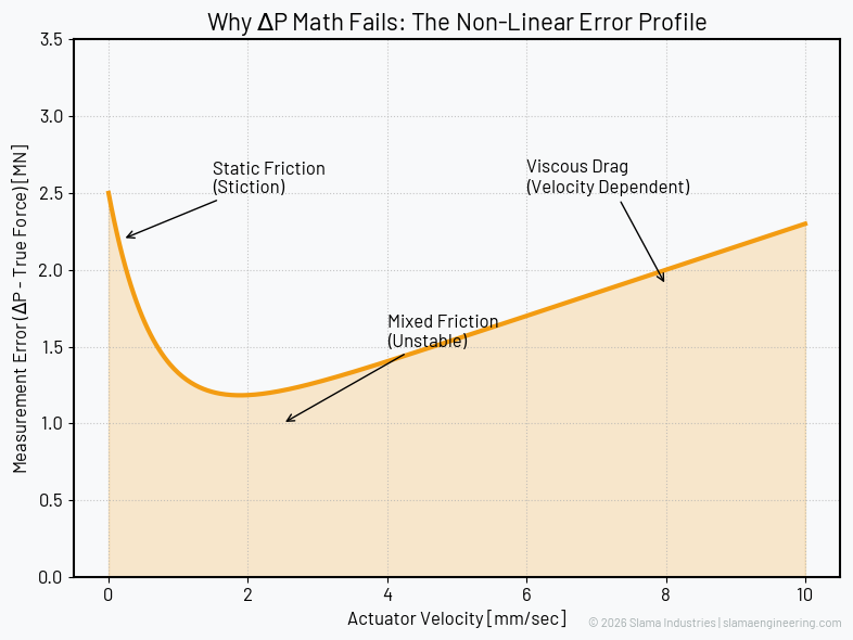
Why can't Data Acquisition (DAQ) software simply subtract the friction? Because hydraulic seal friction is not a constant offset. It is a highly non-linear, multi-variable equation driven by the Stribeck Effect. Attempting to write a compensation matrix for hydraulic stiction is a guessing game.
The Non-Linear Error Profile
Friction shifts dynamically based on actuator velocity, differential fluid pressure, and oil viscosity.
As the cylinder accelerates, the friction transitions unpredictably from severe static friction to unstable mixed friction, and finally into velocity-dependent viscous drag. You cannot "tare" this out. You cannot mathematically compensate for a moving target.
The Direct Measurement Solution
The only mathematical certainty in structural validation is a direct-measurement Wheatstone bridge. Slama Engineering offers high-capacity load cells that bypass the hydraulic circuit entirely. By placing an aerospace-grade transducer directly between the actuator and the test article, we measure the true, uncorrupted mechanical force exactly as the structure experiences it.
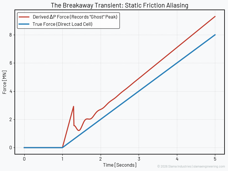
The Breakaway Transient (The "Ghost" Peak)
When a massive hydraulic cylinder starts moving from a dead stop, static friction (stiction) is immense. The hydraulic pressure must spike violently just to break the mechanical seal loose.
To a ΔP measurement system, this pressure buildup looks like a massive force spike hitting your test article. In reality, the test article felt a smooth load, but your DAQ recorded a "Ghost Peak." If your facility is conducting highly sensitive yield or fatigue testing, this aliased data can immediately invalidate a test run.
Validating the Un-Testable (The 4.45 MN Horizon)
The global primary standard for deadweight calibration—housed at NIST—maxes out at 1,000,000 lbf (4.45 MN). When testing at 20 MN or 30 MN, full-scale physical calibration is physically impossible.
We do not claim to "calibrate" beyond this physical limit. Instead, Slama Engineering guarantees full-scale accuracy through FEA-Correlated Extrapolation.
The Correlated Extrapolation Methodology
We build a highly refined Finite Element model to map the exact microstrain output per kN of applied load. We then physically calibrate the manufactured load cell up to the 4.45 MN limit. By proving that the real-world hardware perfectly matches the virtual model's slope within this physical envelope, we can confidently extrapolate the linear output to full capacity.
We maintain this extreme extrapolation confidence through two strict mechanical principles:
Strictly Elastic Geometry: The transducer geometry is heavily over-engineered to remain deep within the linear elastic region well past the maximum rated capacity. By ensuring zero plastic deformation, we guarantee zero non-linear signal deviation.
Zero Micro-Slippage: The primary cause of heavy-tonnage hysteresis is micro-slippage at the mechanical interfaces. We design our bolted joints and load-introduction platens with extreme care, utilizing massive clamp loads to completely eliminate mechanical shift. The slope we validate at 4 MN is the exact same slope you will see at 30 MN.